
Planning a Data System

At some point, when you decide to get a data system, you’re faced with what data to gather. If you have a car where you can tap into the CAN Bus, you’ll probably have all of the info you want with a simple two wire hookup. For those with an older car, you’ll have to start planning on what data you want and how to collect it. Regardless of the brand dash / data logger you’re using, they all accept a multitude of sensors.
When you start to decide on what sensors you want to run, you have a decision. You can normally categorize sensors into two categories – driver development and engine/chassis development. This is where you have to make a decision on what you want out of your system and how much you want to spend.
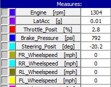
If you want your data system to help you be a better driver, then you want to focus on the sensors that pick up driver inputs. Those will include steering, throttle position, brake pressure, lateral G, Long G, and engine RPM. A very nice extra is to have a GPS antenna over a lap beacon as it will give you the driven line and also work automatically, versus having to put trackside beacon every session. Plus, invariably, you will forget the trackside beacon at the track and have to purchase a replacement (or three).
If you want your data system to help you be a better driver, then you want to focus on the sensors that pick up driver inputs. Those will include steering, throttle position, brake pressure, lateral G, Long G, and engine RPM. A very nice extra is to have a GPS antenna over a lap beacon as it will give you the driven line and also work automatically, versus having to put trackside beacon every session. Plus, invariably, you will forget the trackside beacon at the track and have to purchase a replacement (or three).
Once you have made the decision on what to measure, you have to start planning out the wiring and layout. Most systems have a limited number of channels that can connect directly to the dash. After that, newer systems with CAN buses allow an almost infinite number of additional channel inputs through “junction boxes.” In Motec parlance, these junction boxes are VIMs (Versatile Input Module), in AiM jargon they are Data Hubs and Channel Expansions, and CDS simply refers to them as Junction Boxes or Y Cables.
I find it very helpful to lay out a diagram of what sensors you will have, how many junctions you will have, and the rough position of the sensors. This allows you to plan for how much cabling you will need, where to put junctions, what will hook into the system, and give you a good overall idea of the project ahead of you.
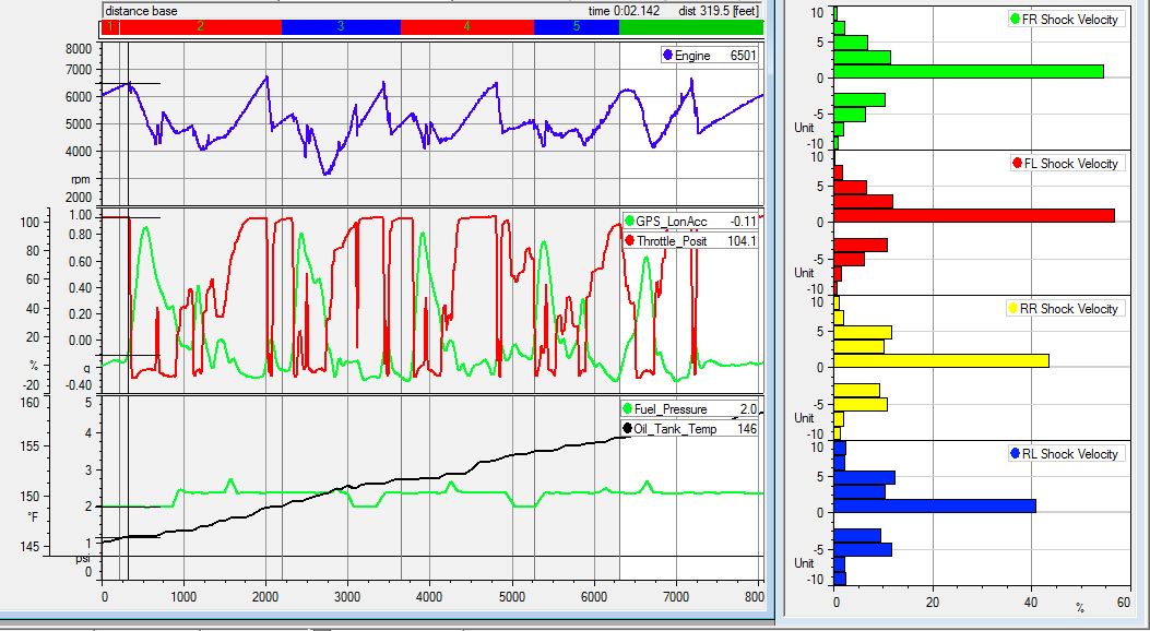
Once this is done, it’s a good idea to double check your plan and make sure that you are configured to match the specifications on your dash. Many systems have limits on what certain channels can do. For instance, in an AiM MXL, wheel speeds must go to a specific channel to go straight into the dash, but can go into a Channel Expansion if the Channels 1 and 2 of the expansion are both set to speed. Some systems also place sampling rate limits on certain channels, so it’s important to plan sensors that will need a high frequency (like shock sensors) to go on the channels that have the highest sampling rates.
This planning, which can be a pretty involved project, will assure that you get the data system you want. It will also help you to hone in on what you want out of your system and make sure you that you have the right sensors and configuration to get the data you need.
I find it very helpful to lay out a diagram of what sensors you will have, how many junctions you will have, and the rough position of the sensors. This allows you to plan for how much cabling you will need, where to put junctions, what will hook into the system, and give you a good overall idea of the project ahead of you.
Once this is done, it’s a good idea to double check your plan and make sure that you are configured to match the specifications on your dash. Many systems have limits on what certain channels can do. For instance, in an AiM MXL, wheel speeds must go to a specific channel to go straight into the dash, but can go into a Channel Expansion if the Channels 1 and 2 of the expansion are both set to speed. Some systems also place sampling rate limits on certain channels, so it’s important to plan sensors that will need a high frequency (like shock sensors) to go on the channels that have the highest sampling rates.
This planning, which can be a pretty involved project, will assure that you get the data system you want. It will also help you to hone in on what you want out of your system and make sure you that you have the right sensors and configuration to get the data you need.
Jan 26th 2021
Recent Posts
-
Position Sensors
So you want to know where something is? There are a lot of options! In motorsports we measure the po …Feb 2nd 2025 -
Pressure Sensor Info
So you want to measure a pressure? Gauge or absolute? Air or liquid? If air, gauge, absolute, or dif …Jan 22nd 2025 -

Driver health, monitoring, and performance
I was surfing Instagram and saw Dr. David Ferguson, of the Spartan Motorsports Performance Lab, post …Mar 22nd 2022